Making PCB’s with Eagle (Post in Progress)
It is inevitable that at some point you will want to create your own PCB. This usually comes about either because you are frustrated with existing hardware and want something better, or because you have some special design that cant be made with readily available parts. Either way creating your own PCB is the end result. I have done this for several years now and figured I would share some best practices and resources to speed up your design process. First though, a little background.
Background:
PCB=Printed Circuit Board, it’s the green board (usually) that all the computer parts are soldered to. There are two types of soldering, Through Hole: where posts of the part go through the board, and SMD (sufrace mount device): where the posts of the part are soldered to the outer layer of the board.
You layout a PCB in a computer program, specifically a CAD program (computer aided design). There are tons of programs out there, some cost a lot of money like Allegro PCB, others cost money but have limited free versions with stripped down capabilities like EAGLE, and others are completely free but tied to a board fab like PCB Artist. A notable exception is a new up and comer called WEB PCB that lets you design your boards on the web.
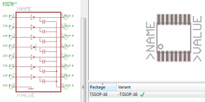
Every PCB CAD program has more or less the same feature set, it lets you create a picture of the electrical connections on the board, this is called a schematic, and a picture of what the board will look like physically, this is called a board layout. Every chip / resistor / capacitor / any device has two pictures, a symbol on the schematic and a package layout on the board file. Together the schematic symbol and the board package layout are refereed to as a device. Package layouts can be the same, ie a 14 pin DIP, but the schematic for that part can vary depending on what it does, it could have a 14pin DIP package and be 7 op-amps, a MSP430, or a 3 USB DAC’s, each of which would have the same package but have completely different symbols. All PCB CAD programs also have a means of holding many devices, usually categorized into Libraries of devices.
Package + Symbol = Device
Library = group of Devices
Once you have designed your PCB you will need to send it off to get made at a PCB fabricator, aka a fab. PCB fab’s are a dime a dozen, some optimize their prices for large boards, some for small, some optimize for through hole parts, some for surface mount parts. The cost of the board will really come down to two things: how many your order, and how big the board is. The bigger the board the more expensive it will be, obviously, but the number you order can actually play a bigger role in how much the boards cost. This is because the majority of PCB production costs are in the overhead of retooling the fab line for new boards, not in actually creating the boards. PCB fab lines are optimized for mass production in great quantities, not many unique small batch jobs. There is a way around this though, if you put a whole lot of small PCB’s together into a larger PCB panel you can send out for several large panels and save money this way. There are several PCB services that do this for you. OSHPark, Seeed Studio, and Midnight Maker (now defunct) to name a few. My favorite for small designs with speedy turnaround time is OSHPark. With 2 layer boards for 5$ per inch for multiples of three and a 2 week turnaround time it just cant be beat for boards under 15″ in total size, above that you may be able to find better deals elsewhere.
How To:
That is all the basic theory behind PCB’s, now I’m going to get into how to create your own. For the rest of this I’m going to assume Eagle as the CAD program and OSHPark as the fab service. It is also assumed you have these libraries installed. Eagle is incredibly well documented and widely used by the maker community, as such I am referencing video’s, How To’s and other material that other people have already generated.
How to make a Device (symbol and package)(Instructables.com)
http://www.instructables.com/id/How-to-make-a-custom-library-part-in-Eagle-CAD-too/?ALLSTEPS
How to Copy / Edit Existing Eagle Parts (Youtube.com)
Move Group in Eagle (Sparkfun.com)
https://forum.sparkfun.com/viewtopic.php?t=10681
How to wire up a Schematic in Eagle (bunch of Symbols wired together)
https://www.youtube.com/watch?v=_l1PRYWCMgc
How to wire up a PCB Layout in Eagle (bunch of Packages wired together)
https://www.youtube.com/watch?v=gRpaU1Eat0U
For parts you can usually get free samples from distributors in small quantities. For example you can get free chips from TI under their samples section (Zigbee, ARM Cortex M3/M4, Bluetooth, USB, etc). You can get free headers / connectors overnighted to you from Samtec (i really like them because they give you 3d models and Eagle files of the parts you order so you can verify they look right and use their Eagle files and not worry about whether or not the part will fit).
For 3D visualization there is a handy plugin called EagleUp, which takes your Eagle files and exports them to Google Sketchup.
or a better writeup on Dangerous Prototypes
http://dangerousprototypes.com/2012/03/20/how-to-build-3d-models-from-eagle-files-wiki-page/